Electrical Wiring Diagrams include the following categories, and the relevant items included in each Category are stated.
Select the item to display from the tree, and display the Electrical Wiring Diagram or System Circuit Diagram. In Electrical Wiring Diagram, lists, and System Circuit Diagrams, parts can be checked on the tree.
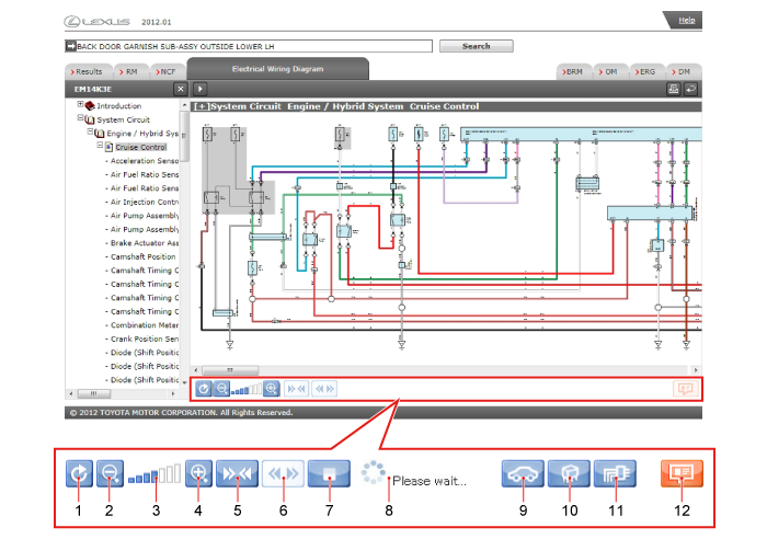
| 1 | Reset
|
||||||||||||||||
|---|---|---|---|---|---|---|---|---|---|---|---|---|---|---|---|---|---|
| 2 | Shorten Pane Reduces the size of the illustration. |
||||||||||||||||
| 3 | Display zoom ratio indicator Displays the display zoom ratio.
|
||||||||||||||||
| 4 | Enlarge Enlarges the size of the illustration. |
||||||||||||||||
| 5 | Compact Display Displays only the circuit diagram for the selected part. For details, see Execute Compact Display. HINT
|
||||||||||||||||
| 6 | Undo Compact Display Undo compact display and display the entire circuit diagram. HINT
|
||||||||||||||||
| 7 | Cancel Compact Display Cancels Compact Display. |
||||||||||||||||
| 8 | Status Display Displays the screen refresh status. |
||||||||||||||||
| 9 | Relocation Displays the Relocation Diagram in which the currently-displayed relay block or junction block is placed. |
||||||||||||||||
| 10 | J/B and R/B diagram Displays the J/B and R/B Diagram that corresponds to the currently displayed Internal Circuit Diagram. |
||||||||||||||||
| 11 | Internal Circuit Diagram Displays the relocation diagram in which the currently-displayed relay block or junction block is placed. |
||||||||||||||||
| 12 | Connectors and Other Details Displays detailed information for connectors relevant to parts selected in the System Circuit Diagram, Relocation Diagram, or Internal Circuit Diagram. |
System Circuit Diagrams consist of Power Supply Circuit Diagrams, Earth Point Circuit Diagrams, and System Circuit Diagrams. Circuit diagrams can be used to check the positions of connectors, wiring harnesses, fuses, relays, etc., and the wiring of systems.
| Select the part or wire and click on the Connectors and Other Details. Connectors and Other Details are displayed for the selected part or for parts connected to the wire. 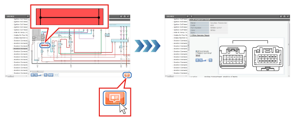 |
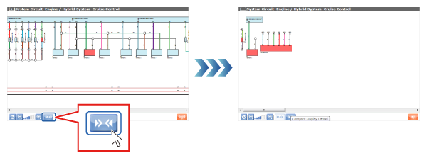
In Compact Display, select multiple wires or parts and switch to a condensed display that only includes the connections between those wires.
Select parts or wires in the System Circuit Diagram and click on the Compact Display button. HINT
|
The fuse list can be used to check the names and capacities of fuses. It can also be used to check which systems are supplied with power by which power supplies.
| Click on the J/B and R/B in the fuse list, or on the button for the fusible link block name. The J/B and R/B Diagram is displayed. 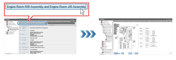 |
| Click on the System name. The System Circuit Diagram is displayed, and the fuses associated with the selected system are displayed flashing. 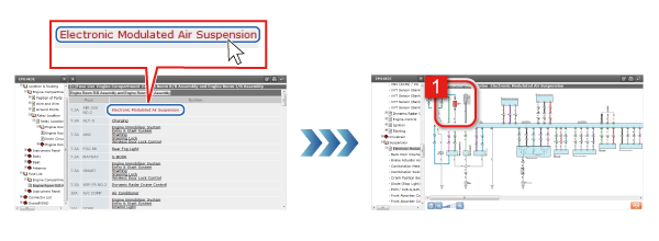 |
The Connectors and Other Details screen can be used to check information such as the parts and connector numbers connected to each connector, and Part Nos. Information can be displayed about Harness Diagrams and System Circuit Diagrams etc. related to connectors.
Click on Repair Wiring Harness to display information about repairing the wiring harness.
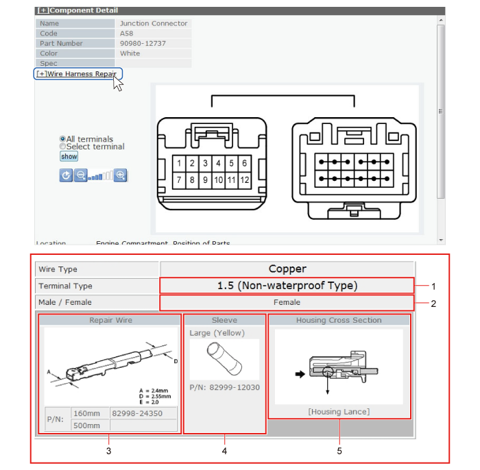
| 1 | Terminal Types |
|---|---|
| 2 | Identification of Male and Female Terminals |
| 3 | Terminal types and Part Nos. |
| 4 | Sleeve forms and Part Nos. |
| 5 | Connector Housing Sectional Diagram |
Items from Harness Diagrams and System Circuit Diagrams can be displayed for all terminals, or only those that are related to the selected terminal.
| Select all terminals and click on Switch Display. All Harness Diagrams and System Circuit Diagrams related to all terminals are displayed. 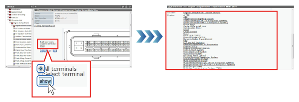 |
| Click on the connector number on the Connector Diagram. The connector number that was clicked on is displayed in red. 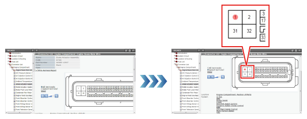 |
| Chose Selected Terminals and click on Switch Display. All Harness Diagrams and System Circuit Diagrams related to the selected connector number are displayed. 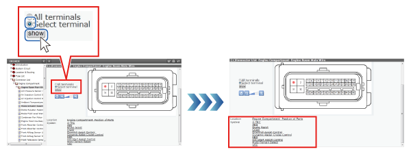 |
| Select a part name and click on the link. The Wiring Harness Diagram is displayed and the connectors of the selected part are displayed flashing. 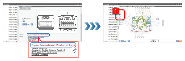 |
| Click on a part name. The System Circuit Diagram is displayed, and the selected part is displayed flashing. 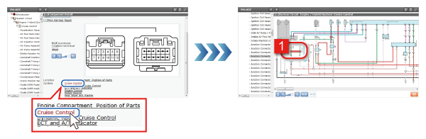 |
Wiring Harness Diagrams can be used to check the mounted positions, earth points, and connector Nos. of the connectors and wiring harness used in all parts of the vehicle.
| Click on a wire name. Display a list of wire names. 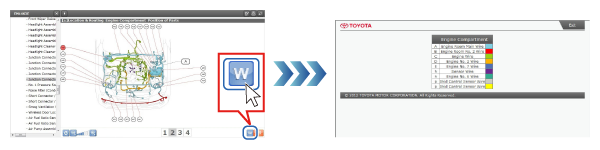 |
| Select the connector number and click on the Connectors and Other Details button. Connectors and Other Details are displayed. 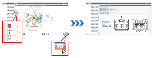 |
J/B and R/B Diagrams can be used to check the positions and other detailed information on the positions of connectors, relays, and fuses that are connected to junction blocks and relay blocks.
| Select the connector number and click on the Relocation button. Relocation is displayed and the part with the selected connector number flashes. 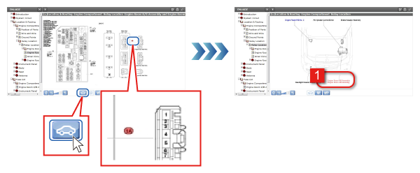 |
| Select a connector number and click on the Internal Circuit Diagram button. The Internal Circuit Diagram is displayed and the selected connector No. is displayed flashing. 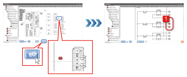 |
| Select the connector number and click on the Connectors and Other Details button. Connectors and Other Details are displayed. 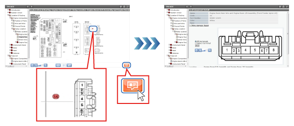 |
Internal Circuit Diagrams can be used to check the internal circuits of junction blocks and relay blocks.
| Select the connector number and click on the Relocation button. Relocation is displayed and the part with the selected connector number flashes. 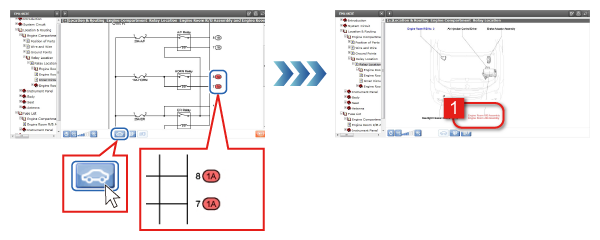 |
| Select a connector number and click on the J/B and R/B Diagram button. The J/B and R/B Diagram is displayed and the selected connector No. is displayed flashing. 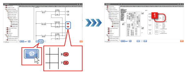 |
| Select the connector number and click on the Connectors and Other Details button. Connectors and Other Details are displayed. 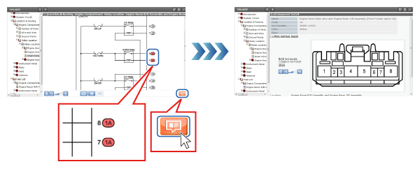 |
Relocation can be used to check the mounted positions on the vehicle of relays, relay blocks, junction blocks, fusible links, computers, etc.
| Select a part name and click on the J/B and R/B button. The J/B and R/B Diagram is displayed. 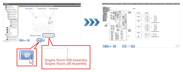 |
| Select a part name and click on the Internal Circuit Diagram button. The Internal Circuit Diagram is displayed and the connector Nos. of the selected part are displayed flashing. 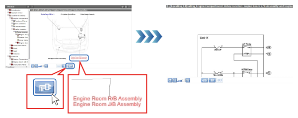 |